- Products & Services
- Commercial Products
- GENERAL INFORMATION
- 3.400 - 3.80 GHZ ANTENNAS
- 4.940 - 5.850 GHZ ANTENNAS
- 57.0-66.0 GHZ ANTENNAS
- 71.0 - 86.0 GHZ ANTENNAS
- 94 GHZ ANTENNAS
- 110 GHZ ANTENNAS
- Custom Products
- C-band Airborne Omnidirectional Antenna
- C-band Dual Linear Polarized Antenna
- C-band & L/S-band Telemetry Horn Antennas
- Custom Ruggedized Antenna Design Capability
- GOES Patch Antenna
- K/Ka-band Co-polarized Conscan Cassegrain Antenna
- K/Ka-band Single Circular Polarized Cassegrain Antenna
- K/Ka-band Dual Circular Polarized Cassegrain Antenna
- L/S/C-band Antenna
- L/S/C-band Antenna Feed
- S-band Dual Linear Portable Antenna
- Telemetry Antennas
- UAV Drone Antenna
- Vertex Mounted Feed
- Wide Band Prime Focus Antenna Feed -
Dual Circular Polarized - Wide Band Prime Focus Antenna Feed - Linear Polarized
- Wide Band UHF Omni Antenna
- X-band Antenna
- X-band Dual CP Antenna
- X-band Portable Antenna
- X-band Shaped Beam Radar Antenna
- 60 GHz, 80 GHz, 94 GHz and 110 GHz Millimeter Wave Antennas
- Testing Services
Model MCR03-04-N Reduced Sized GOES Patch Antenna
Below are two photos along with specifications on mWAVE Industries, LLC model MCR03-04-N reduced sized patch antenna for use with GOES satellites.
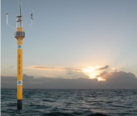
Model MCR03-04-N deployed on platform

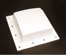
Model MCR03-04-N reduced sized patch

The MCR03-04-N antenna is mounted on the top of a fully operational platform in the left photo. This antenna is used for transmitting data being collected by other instruments on platforms that are recording barometer data, air & sea temperature, wind speed & gusts and wind direction along with other information related to oceanographic measurements. The gathered data is then transmitted to a GOES satellite and sent back to earth. There are hundreds of weather platforms/stations in and around the US that send data that is used for weather tracking/predicting, scientific studies and educational studies just to name a few applications. This antenna was designed for use in high wind and rough sea environments.
Standard patch antennas operating in this frequency band are generally somewhere around 18- 20”across by 6-7” in height. mWAVE’s MCR03-04-N model is only 9”across by 2.75” in height. The radome was manufactured utilizing a UV stabilized heavy wall plastic that can be thermoformed to help keep manufacturing and tooling cost down. There are four clearance holes for 5/16” hardware located near the 4 outside corners of the antenna for mounting. This rugged, reduced sized, easily mounted antenna also makes a good candidate for a quick deployable/portable/replacement antenna when a critical similar antenna site goes down.
| Frequency (MHz) | Gain (dBic) | Axial Ratio (dB) | HPBW (deg.) | F/B (dB) | Return Loss (dB) | Input |
|---|---|---|---|---|---|---|
| 402 | 4.0 | ≤ 3.0 | 112 | >9 | >14.0 | Type N Female |